
Signal Isolator Wiring Diagram
For cars equipped with an alternator, the battery isolator needs to kill the engine by sending a signal to the engine ecu or electronic power distribution module (pdm) or by shutting down the main engine relay. It shows the parts of the circuit as simplified forms and the power and signal links in between the tools.
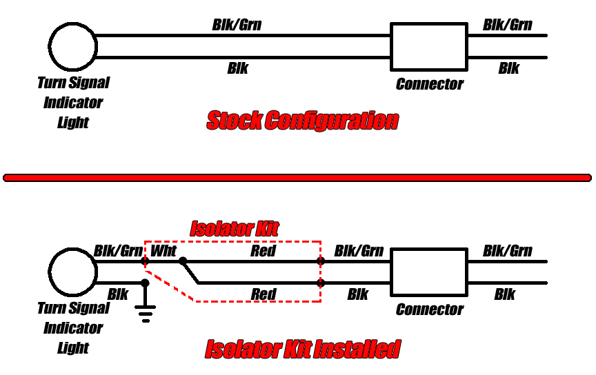
LED Turn Signal Isolator Installation ProCycle.us
A wiring diagram is a streamlined standard pictorial representation of an electric circuit.

Signal isolator wiring diagram. Additionally, an installation diagram shows how to install the module using a compatible electrical box. 3 phase isolator wiring diagram. This is the most complicated of the options to install because you have to wire in a signal to the relay.
3 phase isolator switches are a type of fused switch disconnector mechanism. Crimp on 2 electrical connectors that will attach bat to a. The first step is to figure out the voltage of your phases.
At times, the cables will cross. Fig 2 electrical wiring diagram of three phase single phase consumer unit with rcd wiring color codes of iec and nec. Wiring diagram elektrikal remot lokal.
For battery isolation, you want your relay to activate when the van is running. The engine kill output signal has two states: Diode isolator wiring diagram wiring diagram is a simplified agreeable pictorial representation of an electrical circuit.
Battery isolator switch wiring diagram. In the united states for low voltage motors below 600v you can expect either 230v or 460v. Attach the electronics enclosure to the back left leg tube using the bag 22 sheet metal screws and washers shown.
A wiring diagram is a streamlined conventional pictorial representation of an electric circuit. Solar photovoltaic pv systems use rotary dc isolators with multiple current and voltage ratings more commonly than dc rated circuit breakers. These isolators use several electronic methods for interrupting the two grounds connections while passing an exact signal with accuracy or with a small loss.
Single phase wiring diagrams always use wiring diagram supplied on motor nameplate. It shows the components of the circuit as simplified shapes and the knack and signal associates in the middle of the devices. Optical or galvanic isolation eliminate ground loop errors, reduce noise, and block high voltage transient.
Injunction of 2 wires is generally indicated by black dot at the intersection of two lines. The diagram below shows the conventional placement of the dc. Wiring daigram of remote push button switch to reset an overload.
The best way to do this is to find the "accessory" wire in. There will be primary lines which are represented by l1, l2, l3, and so on. Please choose a year from the menu at left to start your search.
What is a wiring diagram? Assortment of battery isolator wiring schematic. Below you will find the basic design of 3 types of battery isolators with the pros and cons of each.
As stated previous, the traces in a dual battery isolator wiring diagram signifies wires. Rugged rust proof anodized aluminum case. Signal isolator gives electrical isolation among the input &.
But, it doesn't imply connection between the cables. A wiring diagram is an easy visual representation in the physical connections and physical layout of an electrical system or circuit. A 3 pole isolator switch should have 6 connections on it 3 supply 3 load.
A signal isolator "breaks" the galvanic path between two grounds. The plastic isolator shall be oriented so that the bosses fit into the holes in the electronics enclosure. The signal isolator definition is an electrical device which is used to remove earth loop errors which are caused by noise & signal interference problems.
Optoisolator Circuit


HART signal isolator, Galvanic Isolation DAT511H.
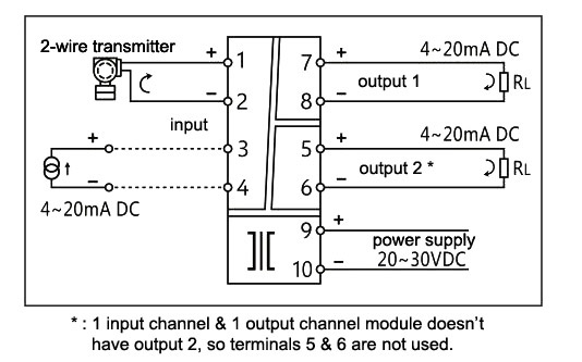
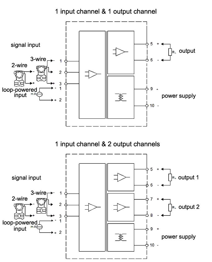
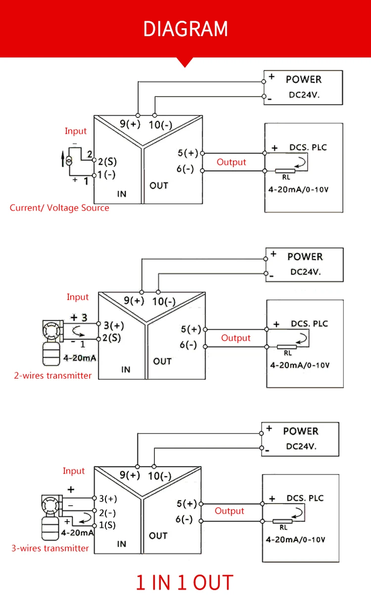
1input1output twowire 420mA loop analog signal isolation transmitter wiring diagram

Battery Isolator Switch Wiring Diagram For Your Needs
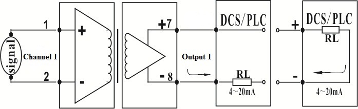
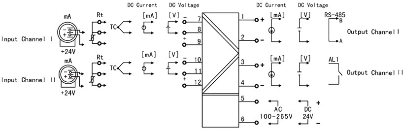
Analog voltage/current signal isolation amplifier module IC application wiring diagram

2Wire LoopPowered DC Signal Isolator 1 In,1 Out. GSSx11x0SB_Current Transducer, voltage

How To Eliminate Ground Loops With Signal Isolation Optically Isolated Usb Hub Wiring Diagram
Linear DC Signal OptoIsolator / Optocoupler Circuit

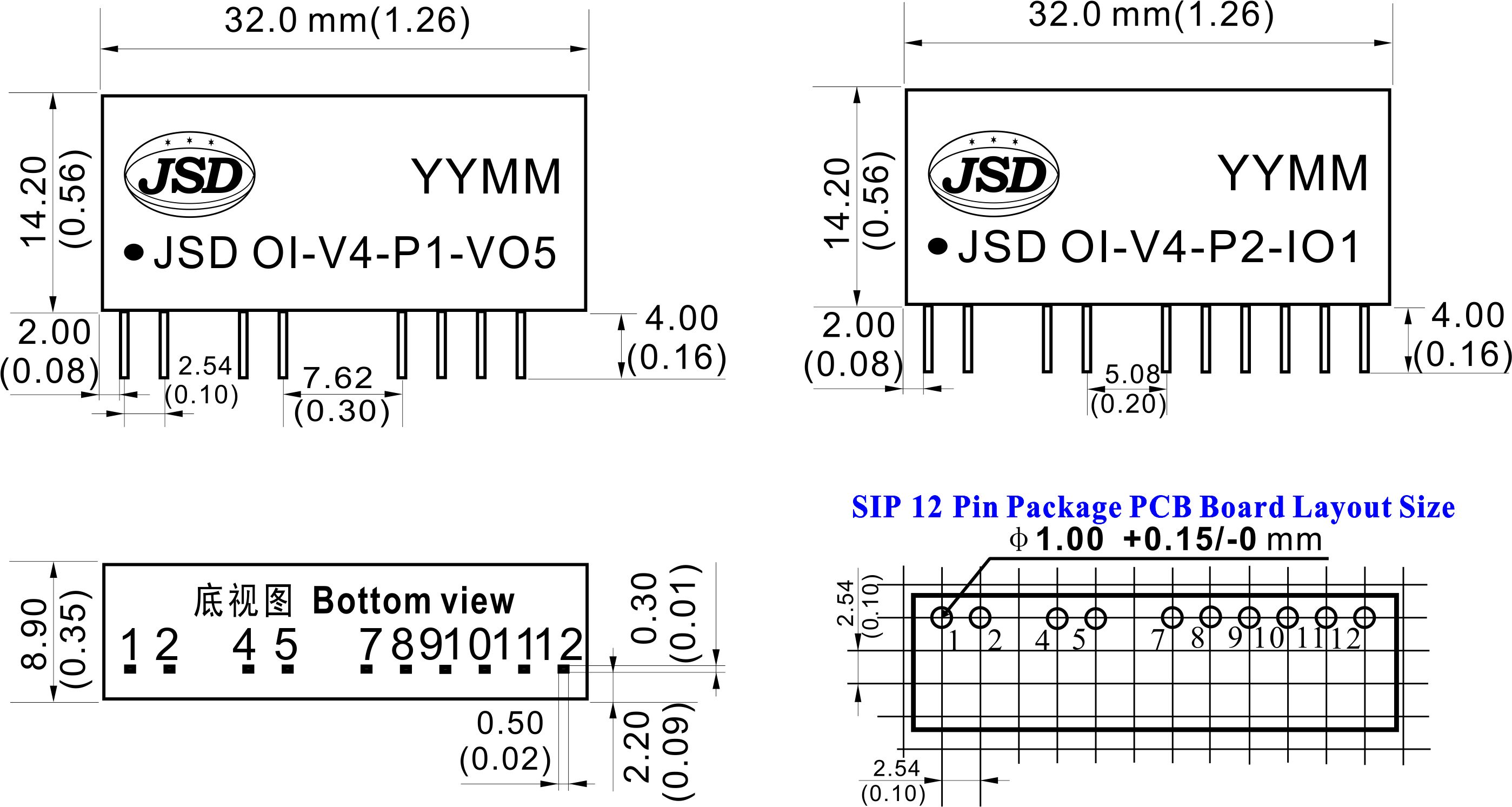
Signal Isolator Input/Output K/B/S/E/PT100/420mA/020mA/15V/010V
Loop Powered Signal Isolator 420mA/020mA/05V/15V/010V with USB
Signal Isolator 420mA with USB, LCD Display, RS485
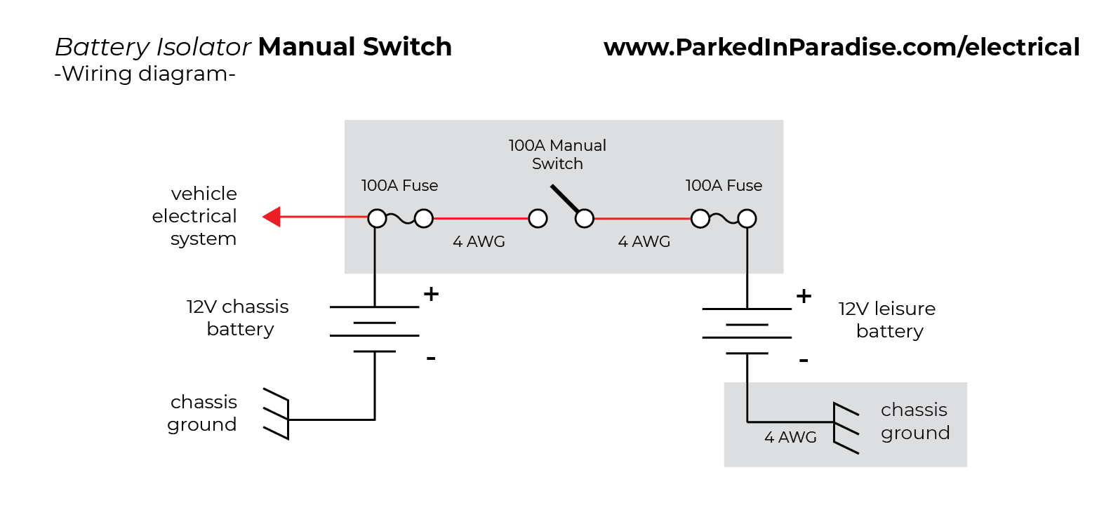
How To Install A Battery Isolator In Your Conversion Van » Parked In Paradise

How To Eliminate Ground Loops With Signal Isolation Optically Isolated Usb Hub Wiring Diagram
Digital Isolation up to 100 Mbits Circuit Diagram

The Ins and Outs of Isolation A Guide to Selecting The Right Instrument Isolator Process
The World Through Electricity Electrical Isolator switch
Gln Galvanic Analog Signal Converter Isolation 420ma Dc 010v Signal Isolator Buy 010v

Ground Loop Isolator Schematic cleverku
Twowire 420mA Current Loop Isolation ConditionerISO 420mAP 420mA020mAIsolator

